Discussion:
power supply idea
(too old to reply)
John Larkin
2024-04-21 22:01:16 UTC
Permalink
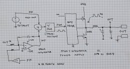
If one had, say, a 48 volt power bus, you could hang a half-bridge
switcher to ground, and a lowpass filter out. If the drive has duty
cycle n, the output voltage is 48*n. So we have a programmable power
supply with no feedback, which will be stable into any load.

The load regulation will be mediocre, but we could almost sell it
as-is.

So now, sense the output voltage and compute the error against the
target, run through a slowish integrator, and tweak the PWM to get
zero output voltage error. Gross transient response is basically the
response of the output filter, with some modest drool from the
integrator.

We can constrain the influence range of the integrator, just enough to
give the regulation that we need. That limits output swing in case the
feedback is wrong, as one could get from a botched remote sense
connection.

Loading Image...
piglet
2024-04-22 07:15:22 UTC
Permalink
Post by John Larkin
If one had, say, a 48 volt power bus, you could hang a half-bridge
switcher to ground, and a lowpass filter out. If the drive has duty
cycle n, the output voltage is 48*n. So we have a programmable power
supply with no feedback, which will be stable into any load.
The load regulation will be mediocre, but we could almost sell it
as-is.
So now, sense the output voltage and compute the error against the
target, run through a slowish integrator, and tweak the PWM to get
zero output voltage error. Gross transient response is basically the
response of the output filter, with some modest drool from the
integrator.
We can constrain the influence range of the integrator, just enough to
give the regulation that we need. That limits output swing in case the
feedback is wrong, as one could get from a botched remote sense
connection.
https://www.dropbox.com/scl/fi/2fysyvkl4eim7vujhaobh/FFINT_PS_1.jpg?rlkey=rug6yi3cgemi9vvbz8apgboqi&raw=1
Looks like you have invented the buck converter.
--
piglet
John Larkin
2024-04-22 15:50:02 UTC
Permalink
On Mon, 22 Apr 2024 07:15:22 -0000 (UTC), piglet
Post by piglet
Post by John Larkin
If one had, say, a 48 volt power bus, you could hang a half-bridge
switcher to ground, and a lowpass filter out. If the drive has duty
cycle n, the output voltage is 48*n. So we have a programmable power
supply with no feedback, which will be stable into any load.
The load regulation will be mediocre, but we could almost sell it
as-is.
So now, sense the output voltage and compute the error against the
target, run through a slowish integrator, and tweak the PWM to get
zero output voltage error. Gross transient response is basically the
response of the output filter, with some modest drool from the
integrator.
We can constrain the influence range of the integrator, just enough to
give the regulation that we need. That limits output swing in case the
feedback is wrong, as one could get from a botched remote sense
connection.
https://www.dropbox.com/scl/fi/2fysyvkl4eim7vujhaobh/FFINT_PS_1.jpg?rlkey=rug6yi3cgemi9vvbz8apgboqi&raw=1
Looks like you have invented the buck converter.
I invented a control algorithm. All the buck chips that I know of are
all feedback driven, and will slam into either rail if the feedback
divider is broken. Blow things up.
Don
2024-04-22 17:38:19 UTC
Permalink
Post by John Larkin
Post by piglet
Post by John Larkin
If one had, say, a 48 volt power bus, you could hang a half-bridge
switcher to ground, and a lowpass filter out. If the drive has duty
cycle n, the output voltage is 48*n. So we have a programmable power
supply with no feedback, which will be stable into any load.
The load regulation will be mediocre, but we could almost sell it
as-is.
So now, sense the output voltage and compute the error against the
target, run through a slowish integrator, and tweak the PWM to get
zero output voltage error. Gross transient response is basically the
response of the output filter, with some modest drool from the
integrator.
We can constrain the influence range of the integrator, just enough to
give the regulation that we need. That limits output swing in case the
feedback is wrong, as one could get from a botched remote sense
connection.
https://www.dropbox.com/scl/fi/2fysyvkl4eim7vujhaobh/FFINT_PS_1.jpg?rlkey=rug6yi3cgemi9vvbz8apgboqi&raw=1
Looks like you have invented the buck converter.
I invented a control algorithm. All the buck chips that I know of are
all feedback driven, and will slam into either rail if the feedback
divider is broken. Blow things up.
An algorithm arguably eliminates a 555 triangle generator as a potential
spread spectrum source. LOL. So, what's hidden in plain sight behind all
of your left hand side, symbolic sleight of hand? In other words, how do
you implement your control algorithm?

Danke,
--
Don, KB7RPU, https://www.qsl.net/kb7rpu
There was a young lady named Bright Whose speed was far faster than light;
She set out one day In a relative way And returned on the previous night.
John Larkin
2024-04-22 18:09:57 UTC
Permalink
Post by Don
Post by John Larkin
Post by piglet
Post by John Larkin
If one had, say, a 48 volt power bus, you could hang a half-bridge
switcher to ground, and a lowpass filter out. If the drive has duty
cycle n, the output voltage is 48*n. So we have a programmable power
supply with no feedback, which will be stable into any load.
The load regulation will be mediocre, but we could almost sell it
as-is.
So now, sense the output voltage and compute the error against the
target, run through a slowish integrator, and tweak the PWM to get
zero output voltage error. Gross transient response is basically the
response of the output filter, with some modest drool from the
integrator.
We can constrain the influence range of the integrator, just enough to
give the regulation that we need. That limits output swing in case the
feedback is wrong, as one could get from a botched remote sense
connection.
https://www.dropbox.com/scl/fi/2fysyvkl4eim7vujhaobh/FFINT_PS_1.jpg?rlkey=rug6yi3cgemi9vvbz8apgboqi&raw=1
Looks like you have invented the buck converter.
I invented a control algorithm. All the buck chips that I know of are
all feedback driven, and will slam into either rail if the feedback
divider is broken. Blow things up.
An algorithm arguably eliminates a 555 triangle generator as a potential
spread spectrum source. LOL. So, what's hidden in plain sight behind all
of your left hand side, symbolic sleight of hand? In other words, how do
you implement your control algorithm?
Danke,
It's all in plain sight. Well, the guts of the PWM converter isn't,
but that's pretty obvious.

The PWM converter, and in fact everything, will be implemented in an
FPGA, with an ADC to pick up the output voltage.

May as well go pseudo-random on the spread spectrum part. Any audible
side effects would be hiss, not whine.
Klaus Vestergaard Kragelund
2024-04-23 21:47:26 UTC
Permalink
Post by John Larkin
Post by Don
Post by John Larkin
Post by piglet
Post by John Larkin
If one had, say, a 48 volt power bus, you could hang a half-bridge
switcher to ground, and a lowpass filter out. If the drive has duty
cycle n, the output voltage is 48*n. So we have a programmable power
supply with no feedback, which will be stable into any load.
The load regulation will be mediocre, but we could almost sell it
as-is.
So now, sense the output voltage and compute the error against the
target, run through a slowish integrator, and tweak the PWM to get
zero output voltage error. Gross transient response is basically the
response of the output filter, with some modest drool from the
integrator.
We can constrain the influence range of the integrator, just enough to
give the regulation that we need. That limits output swing in case the
feedback is wrong, as one could get from a botched remote sense
connection.
https://www.dropbox.com/scl/fi/2fysyvkl4eim7vujhaobh/FFINT_PS_1.jpg?rlkey=rug6yi3cgemi9vvbz8apgboqi&raw=1
Looks like you have invented the buck converter.
I invented a control algorithm. All the buck chips that I know of are
all feedback driven, and will slam into either rail if the feedback
divider is broken. Blow things up.
An algorithm arguably eliminates a 555 triangle generator as a potential
spread spectrum source. LOL. So, what's hidden in plain sight behind all
of your left hand side, symbolic sleight of hand? In other words, how do
you implement your control algorithm?
Danke,
It's all in plain sight. Well, the guts of the PWM converter isn't,
but that's pretty obvious.
The PWM converter, and in fact everything, will be implemented in an
FPGA, with an ADC to pick up the output voltage.
May as well go pseudo-random on the spread spectrum part. Any audible
side effects would be hiss, not whine.
I have done what you propose, but I did not add the spread-spectrum part.

If you add a current sense on the output, you can characterize the
non-linearity of the power stage, and do feedforward compensation. So
your response will be snappy. You still have the settle time of the LC
filter, that's harder to counteract with feedforward.
Klaus Vestergaard Kragelund
2024-04-23 21:56:44 UTC
Permalink
Post by Klaus Vestergaard Kragelund
Post by John Larkin
Post by Don
Post by John Larkin
Post by piglet
Post by John Larkin
If one had, say, a 48 volt power bus, you could hang a half-bridge
switcher to ground, and a lowpass filter out. If the drive has duty
cycle n, the output voltage is 48*n. So we have a programmable power
supply with no feedback, which will be stable into any load.
The load regulation will be mediocre, but we could almost sell it
as-is.
So now, sense the output voltage and compute the error against the
target, run through a slowish integrator, and tweak the PWM to get
zero output voltage error. Gross transient response is basically the
response of the output filter, with some modest drool from the
integrator.
We can constrain the influence range of the integrator, just enough to
give the regulation that we need. That limits output swing in case the
feedback is wrong, as one could get from a botched remote sense
connection.
https://www.dropbox.com/scl/fi/2fysyvkl4eim7vujhaobh/FFINT_PS_1.jpg?rlkey=rug6yi3cgemi9vvbz8apgboqi&raw=1
Looks like you have invented the buck converter.
I invented a control algorithm. All the buck chips that I know of are
all feedback driven, and will slam into either rail if the feedback
divider is broken. Blow things up.
An algorithm arguably eliminates a 555 triangle generator as a potential
spread spectrum source. LOL. So, what's hidden in plain sight behind all
of your left hand side, symbolic sleight of hand? In other words, how do
you implement your control algorithm?
Danke,
It's all in plain sight. Well, the guts of the PWM converter isn't,
but that's pretty obvious.
The PWM converter, and in fact everything, will be implemented in an
FPGA, with an ADC to pick up the output voltage.
May as well go pseudo-random on the spread spectrum part. Any audible
side effects would be hiss, not whine.
I have done what you propose, but I did not add the spread-spectrum part.
If you add a current sense on the output, you can characterize the
non-linearity of the power stage, and do feedforward compensation. So
your response will be snappy. You still have the settle time of the LC
filter, that's harder to counteract with feedforward.
One concept I never had time to implement, was to do in circuit
compensation. So in your function test, add a swept current load on the
output at different output voltages, and feed the results to the
feedforward lookup table. That will take care of variations on
components, albeit wont reduce temperature affected errors.
john larkin
2024-04-23 23:17:15 UTC
Permalink
On Tue, 23 Apr 2024 23:56:44 +0200, Klaus Vestergaard Kragelund
Post by Klaus Vestergaard Kragelund
Post by John Larkin
Post by Don
Post by John Larkin
Post by piglet
Post by John Larkin
If one had, say, a 48 volt power bus, you could hang a half-bridge
switcher to ground, and a lowpass filter out. If the drive has duty
cycle n, the output voltage is 48*n. So we have a programmable power
supply with no feedback, which will be stable into any load.
The load regulation will be mediocre, but we could almost sell it
as-is.
So now, sense the output voltage and compute the error against the
target, run through a slowish integrator, and tweak the PWM to get
zero output voltage error. Gross transient response is basically the
response of the output filter, with some modest drool from the
integrator.
We can constrain the influence range of the integrator, just enough to
give the regulation that we need. That limits output swing in case the
feedback is wrong, as one could get from a botched remote sense
connection.
https://www.dropbox.com/scl/fi/2fysyvkl4eim7vujhaobh/FFINT_PS_1.jpg?rlkey=rug6yi3cgemi9vvbz8apgboqi&raw=1
Looks like you have invented the buck converter.
I invented a control algorithm. All the buck chips that I know of are
all feedback driven, and will slam into either rail if the feedback
divider is broken. Blow things up.
An algorithm arguably eliminates a 555 triangle generator as a potential
spread spectrum source. LOL. So, what's hidden in plain sight behind all
of your left hand side, symbolic sleight of hand? In other words, how do
you implement your control algorithm?
Danke,
It's all in plain sight. Well, the guts of the PWM converter isn't,
but that's pretty obvious.
The PWM converter, and in fact everything, will be implemented in an
FPGA, with an ADC to pick up the output voltage.
May as well go pseudo-random on the spread spectrum part. Any audible
side effects would be hiss, not whine.
I have done what you propose, but I did not add the spread-spectrum part.
If you add a current sense on the output, you can characterize the
non-linearity of the power stage, and do feedforward compensation. So
your response will be snappy. You still have the settle time of the LC
filter, that's harder to counteract with feedforward.
One concept I never had time to implement, was to do in circuit
compensation. So in your function test, add a swept current load on the
output at different output voltages, and feed the results to the
feedforward lookup table. That will take care of variations on
components, albeit wont reduce temperature affected errors.
One of our applications has a fixed, stiff 48 volt supply. So we
could characterize the switcher output as an ohmic source, and use the
sensed current to null out most or all of those ohms, so the
integrator can have an even smaller influence range. Or even no
integrator! We need a current sensor anyhow.

Another product will have an isolated dc/dc converter driving the
half-bridge, and it will be fairly soft, nonlinear at that. We will
digitize that 60 volt supply anyhow, so it and the current together
could be compensated. That might require a divide in the FPGA. I'll
ask my FPGA kids if they can divide.
Klaus Vestergaard Kragelund
2024-04-23 23:52:51 UTC
Permalink
Post by john larkin
On Tue, 23 Apr 2024 23:56:44 +0200, Klaus Vestergaard Kragelund
Post by Klaus Vestergaard Kragelund
Post by John Larkin
Post by Don
Post by John Larkin
Post by piglet
Post by John Larkin
If one had, say, a 48 volt power bus, you could hang a half-bridge
switcher to ground, and a lowpass filter out. If the drive has duty
cycle n, the output voltage is 48*n. So we have a programmable power
supply with no feedback, which will be stable into any load.
The load regulation will be mediocre, but we could almost sell it
as-is.
So now, sense the output voltage and compute the error against the
target, run through a slowish integrator, and tweak the PWM to get
zero output voltage error. Gross transient response is basically the
response of the output filter, with some modest drool from the
integrator.
We can constrain the influence range of the integrator, just enough to
give the regulation that we need. That limits output swing in case the
feedback is wrong, as one could get from a botched remote sense
connection.
https://www.dropbox.com/scl/fi/2fysyvkl4eim7vujhaobh/FFINT_PS_1.jpg?rlkey=rug6yi3cgemi9vvbz8apgboqi&raw=1
Looks like you have invented the buck converter.
I invented a control algorithm. All the buck chips that I know of are
all feedback driven, and will slam into either rail if the feedback
divider is broken. Blow things up.
An algorithm arguably eliminates a 555 triangle generator as a potential
spread spectrum source. LOL. So, what's hidden in plain sight behind all
of your left hand side, symbolic sleight of hand? In other words, how do
you implement your control algorithm?
Danke,
It's all in plain sight. Well, the guts of the PWM converter isn't,
but that's pretty obvious.
The PWM converter, and in fact everything, will be implemented in an
FPGA, with an ADC to pick up the output voltage.
May as well go pseudo-random on the spread spectrum part. Any audible
side effects would be hiss, not whine.
I have done what you propose, but I did not add the spread-spectrum part.
If you add a current sense on the output, you can characterize the
non-linearity of the power stage, and do feedforward compensation. So
your response will be snappy. You still have the settle time of the LC
filter, that's harder to counteract with feedforward.
One concept I never had time to implement, was to do in circuit
compensation. So in your function test, add a swept current load on the
output at different output voltages, and feed the results to the
feedforward lookup table. That will take care of variations on
components, albeit wont reduce temperature affected errors.
One of our applications has a fixed, stiff 48 volt supply. So we
could characterize the switcher output as an ohmic source, and use the
sensed current to null out most or all of those ohms, so the
integrator can have an even smaller influence range. Or even no
integrator! We need a current sensor anyhow.
Sounds like a fun project. You could do this with a 0.3 USD ARM CM0
processor, but I guess you have the FPGA on the board anyhow.
Post by john larkin
Another product will have an isolated dc/dc converter driving the
half-bridge, and it will be fairly soft, nonlinear at that. We will
digitize that 60 volt supply anyhow, so it and the current together
could be compensated. That might require a divide in the FPGA. I'll
ask my FPGA kids if they can divide.
Lasse Langwadt
2024-04-24 19:16:19 UTC
Permalink
Post by john larkin
On Tue, 23 Apr 2024 23:56:44 +0200, Klaus Vestergaard Kragelund
Post by Klaus Vestergaard Kragelund
Post by John Larkin
Post by Don
Post by John Larkin
Post by piglet
Post by John Larkin
If one had, say, a 48 volt power bus, you could hang a half-bridge
switcher to ground, and a lowpass filter out. If the drive has duty
cycle n, the output voltage is 48*n. So we have a programmable power
supply with no feedback, which will be stable into any load.
The load regulation will be mediocre, but we could almost sell it
as-is.
So now, sense the output voltage and compute the error against the
target, run through a slowish integrator, and tweak the PWM to get
zero output voltage error. Gross transient response is basically the
response of the output filter, with some modest drool from the
integrator.
We can constrain the influence range of the integrator, just enough to
give the regulation that we need. That limits output swing in case the
feedback is wrong, as one could get from a botched remote sense
connection.
https://www.dropbox.com/scl/fi/2fysyvkl4eim7vujhaobh/FFINT_PS_1.jpg?rlkey=rug6yi3cgemi9vvbz8apgboqi&raw=1
Looks like you have invented the buck converter.
I invented a control algorithm. All the buck chips that I know of are
all feedback driven, and will slam into either rail if the feedback
divider is broken. Blow things up.
An algorithm arguably eliminates a 555 triangle generator as a potential
spread spectrum source. LOL. So, what's hidden in plain sight behind all
of your left hand side, symbolic sleight of hand? In other words, how do
you implement your control algorithm?
Danke,
It's all in plain sight. Well, the guts of the PWM converter isn't,
but that's pretty obvious.
The PWM converter, and in fact everything, will be implemented in an
FPGA, with an ADC to pick up the output voltage.
May as well go pseudo-random on the spread spectrum part. Any audible
side effects would be hiss, not whine.
I have done what you propose, but I did not add the spread-spectrum part.
If you add a current sense on the output, you can characterize the
non-linearity of the power stage, and do feedforward compensation. So
your response will be snappy. You still have the settle time of the LC
filter, that's harder to counteract with feedforward.
One concept I never had time to implement, was to do in circuit
compensation. So in your function test, add a swept current load on the
output at different output voltages, and feed the results to the
feedforward lookup table. That will take care of variations on
components, albeit wont reduce temperature affected errors.
One of our applications has a fixed, stiff 48 volt supply. So we
could characterize the switcher output as an ohmic source, and use the
sensed current to null out most or all of those ohms, so the
integrator can have an even smaller influence range. Or even no
integrator! We need a current sensor anyhow.
Another product will have an isolated dc/dc converter driving the
half-bridge, and it will be fairly soft, nonlinear at that. We will
digitize that 60 volt supply anyhow, so it and the current together
could be compensated. That might require a divide in the FPGA. I'll
ask my FPGA kids if they can divide.
division is just like any other operation, it just takes more cycles
since since it can't be done in parallel like a multiply
Liz Tuddenham
2024-04-22 10:10:41 UTC
Permalink
Post by John Larkin
If one had, say, a 48 volt power bus, you could hang a half-bridge
switcher to ground, and a lowpass filter out. If the drive has duty
cycle n, the output voltage is 48*n. So we have a programmable power
supply with no feedback, which will be stable into any load.
The load regulation will be mediocre, but we could almost sell it
as-is.
So now, sense the output voltage and compute the error against the
target, run through a slowish integrator, and tweak the PWM to get
zero output voltage error. Gross transient response is basically the
response of the output filter, with some modest drool from the
integrator.
In thory, pulse-width contol of the output could give excellent
stability under load -- but the filter is going to cause droop. Unless
you are very careful about the design of the filter, the phase shifts it
creates will make the feedback loop unstable. An integrator in the loop
will stabilise this at the expense of a much slower response time.

Somewhere in the loop you need a dominant pole so that (to use audio
amplifier terminology) your roll-off is 6dB per octave until the loop
gain has dropped far enough for stability when all the other phase
shifts kick in and the slope increases to 12dB per octave or more.
Rather than integrating the feedback, transferring the dominant pole to
the filter will result in less output noise and a faster response to a
step increase in the load.
--
~ Liz Tuddenham ~
(Remove the ".invalid"s and add ".co.uk" to reply)
www.poppyrecords.co.uk
John Larkin
2024-04-22 15:53:45 UTC
Permalink
Post by Liz Tuddenham
Post by John Larkin
If one had, say, a 48 volt power bus, you could hang a half-bridge
switcher to ground, and a lowpass filter out. If the drive has duty
cycle n, the output voltage is 48*n. So we have a programmable power
supply with no feedback, which will be stable into any load.
The load regulation will be mediocre, but we could almost sell it
as-is.
So now, sense the output voltage and compute the error against the
target, run through a slowish integrator, and tweak the PWM to get
zero output voltage error. Gross transient response is basically the
response of the output filter, with some modest drool from the
integrator.
In thory, pulse-width contol of the output could give excellent
stability under load -- but the filter is going to cause droop. Unless
you are very careful about the design of the filter, the phase shifts it
creates will make the feedback loop unstable. An integrator in the loop
will stabilise this at the expense of a much slower response time.
Somewhere in the loop you need a dominant pole so that (to use audio
amplifier terminology) your roll-off is 6dB per octave until the loop
gain has dropped far enough for stability when all the other phase
shifts kick in and the slope increases to 12dB per octave or more.
Rather than integrating the feedback, transferring the dominant pole to
the filter will result in less output noise and a faster response to a
step increase in the load.
An LC filter is at least 2-pole, usually more, and we have no idea
what crazy stuff the customer might connect to our power supply. So
the less we depend of feedback from the output, the safer things get.

A power supply without feedback is always stable.
Liz Tuddenham
2024-04-22 16:30:40 UTC
Permalink
Post by John Larkin
Post by Liz Tuddenham
Post by John Larkin
If one had, say, a 48 volt power bus, you could hang a half-bridge
switcher to ground, and a lowpass filter out. If the drive has duty
cycle n, the output voltage is 48*n. So we have a programmable power
supply with no feedback, which will be stable into any load.
The load regulation will be mediocre, but we could almost sell it
as-is.
So now, sense the output voltage and compute the error against the
target, run through a slowish integrator, and tweak the PWM to get
zero output voltage error. Gross transient response is basically the
response of the output filter, with some modest drool from the
integrator.
In thory, pulse-width contol of the output could give excellent
stability under load -- but the filter is going to cause droop. Unless
you are very careful about the design of the filter, the phase shifts it
creates will make the feedback loop unstable. An integrator in the loop
will stabilise this at the expense of a much slower response time.
Somewhere in the loop you need a dominant pole so that (to use audio
amplifier terminology) your roll-off is 6dB per octave until the loop
gain has dropped far enough for stability when all the other phase
shifts kick in and the slope increases to 12dB per octave or more.
Rather than integrating the feedback, transferring the dominant pole to
the filter will result in less output noise and a faster response to a
step increase in the load.
An LC filter is at least 2-pole, usually more,
If you made it three poles, with one of them significantly lower
frequency than the other two, stability would be much easier to obtain.
--
~ Liz Tuddenham ~
(Remove the ".invalid"s and add ".co.uk" to reply)
www.poppyrecords.co.uk
John Larkin
2024-04-22 19:16:07 UTC
Permalink
Post by Liz Tuddenham
Post by John Larkin
Post by Liz Tuddenham
Post by John Larkin
If one had, say, a 48 volt power bus, you could hang a half-bridge
switcher to ground, and a lowpass filter out. If the drive has duty
cycle n, the output voltage is 48*n. So we have a programmable power
supply with no feedback, which will be stable into any load.
The load regulation will be mediocre, but we could almost sell it
as-is.
So now, sense the output voltage and compute the error against the
target, run through a slowish integrator, and tweak the PWM to get
zero output voltage error. Gross transient response is basically the
response of the output filter, with some modest drool from the
integrator.
In thory, pulse-width contol of the output could give excellent
stability under load -- but the filter is going to cause droop. Unless
you are very careful about the design of the filter, the phase shifts it
creates will make the feedback loop unstable. An integrator in the loop
will stabilise this at the expense of a much slower response time.
Somewhere in the loop you need a dominant pole so that (to use audio
amplifier terminology) your roll-off is 6dB per octave until the loop
gain has dropped far enough for stability when all the other phase
shifts kick in and the slope increases to 12dB per octave or more.
Rather than integrating the feedback, transferring the dominant pole to
the filter will result in less output noise and a faster response to a
step increase in the load.
An LC filter is at least 2-pole, usually more,
If you made it three poles, with one of them significantly lower
frequency than the other two, stability would be much easier to obtain.
Capacitor ESR, native or added, helps.

I also want to kill the Q as seen from the load side, so it doesn't
ring much if they switch an inductive load.

The load-from-hell is of course some box with a switching regulator
power supply, that looks like a negative resistance load.
Don
2024-04-22 12:57:22 UTC
Permalink
Post by John Larkin
If one had, say, a 48 volt power bus, you could hang a half-bridge
switcher to ground, and a lowpass filter out. If the drive has duty
cycle n, the output voltage is 48*n. So we have a programmable power
supply with no feedback, which will be stable into any load.
The load regulation will be mediocre, but we could almost sell it
as-is.
So now, sense the output voltage and compute the error against the
target, run through a slowish integrator, and tweak the PWM to get
zero output voltage error. Gross transient response is basically the
response of the output filter, with some modest drool from the
integrator.
We can constrain the influence range of the integrator, just enough to
give the regulation that we need. That limits output swing in case the
feedback is wrong, as one could get from a botched remote sense
connection.
https://www.dropbox.com/scl/fi/2fysyvkl4eim7vujhaobh/FFINT_PS_1.jpg?rlkey=rug6yi3cgemi9vvbz8apgboqi&raw=1
Is your "spread spectrum" dodad supposed to mitigate EMI?

Danke,
--
Don, KB7RPU, https://www.qsl.net/kb7rpu
There was a young lady named Bright Whose speed was far faster than light;
She set out one day In a relative way And returned on the previous night.
Bill Sloman
2024-04-22 15:09:10 UTC
Permalink
Post by Don
Post by John Larkin
If one had, say, a 48 volt power bus, you could hang a half-bridge
switcher to ground, and a lowpass filter out. If the drive has duty
cycle n, the output voltage is 48*n. So we have a programmable power
supply with no feedback, which will be stable into any load.
The load regulation will be mediocre, but we could almost sell it
as-is.
So now, sense the output voltage and compute the error against the
target, run through a slowish integrator, and tweak the PWM to get
zero output voltage error. Gross transient response is basically the
response of the output filter, with some modest drool from the
integrator.
We can constrain the influence range of the integrator, just enough to
give the regulation that we need. That limits output swing in case the
feedback is wrong, as one could get from a botched remote sense
connection.
https://www.dropbox.com/scl/fi/2fysyvkl4eim7vujhaobh/FFINT_PS_1.jpg?rlkey=rug6yi3cgemi9vvbz8apgboqi&raw=1
Is your "spread spectrum" dodad supposed to mitigate EMI?
It smears it out over a range of frequencies, and makes it look better
on the screen - no big frequency spikes, but many more smaller ones.

"Mitigate" depends on how the hash messes up your particular system.
--
Bill Sloman, Sydney
John R Walliker
2024-04-22 15:32:00 UTC
Permalink
Post by Bill Sloman
Post by Don
Post by John Larkin
If one had, say, a 48 volt power bus, you could hang a half-bridge
switcher to ground, and a lowpass filter out. If the drive has duty
cycle n, the output voltage is 48*n. So we have a programmable power
supply with no feedback, which will be stable into any load.
The load regulation will be mediocre, but we could almost sell it
as-is.
So now, sense the output voltage and compute the error against the
target, run through a slowish integrator, and tweak the PWM to get
zero output voltage error. Gross transient response is basically the
response of the output filter, with some modest drool from the
integrator.
We can constrain the influence range of the integrator, just enough to
give the regulation that we need. That limits output swing in case the
feedback is wrong, as one could get from a botched remote sense
connection.
https://www.dropbox.com/scl/fi/2fysyvkl4eim7vujhaobh/FFINT_PS_1.jpg?rlkey=rug6yi3cgemi9vvbz8apgboqi&raw=1
Is your "spread spectrum" dodad supposed to mitigate EMI?
It smears it out over a range of frequencies, and makes it look better
on the screen - no big frequency spikes, but many more smaller ones.
"Mitigate" depends on how the hash messes up your particular system.
Yes, but the only one that most designers care about is the EMC
receiver at the compliance test lab.

John
John Larkin
2024-04-22 16:04:21 UTC
Permalink
On Mon, 22 Apr 2024 16:32:00 +0100, John R Walliker
Post by John R Walliker
Post by Bill Sloman
Post by Don
Post by John Larkin
If one had, say, a 48 volt power bus, you could hang a half-bridge
switcher to ground, and a lowpass filter out. If the drive has duty
cycle n, the output voltage is 48*n. So we have a programmable power
supply with no feedback, which will be stable into any load.
The load regulation will be mediocre, but we could almost sell it
as-is.
So now, sense the output voltage and compute the error against the
target, run through a slowish integrator, and tweak the PWM to get
zero output voltage error. Gross transient response is basically the
response of the output filter, with some modest drool from the
integrator.
We can constrain the influence range of the integrator, just enough to
give the regulation that we need. That limits output swing in case the
feedback is wrong, as one could get from a botched remote sense
connection.
https://www.dropbox.com/scl/fi/2fysyvkl4eim7vujhaobh/FFINT_PS_1.jpg?rlkey=rug6yi3cgemi9vvbz8apgboqi&raw=1
Is your "spread spectrum" dodad supposed to mitigate EMI?
It smears it out over a range of frequencies, and makes it look better
on the screen - no big frequency spikes, but many more smaller ones.
"Mitigate" depends on how the hash messes up your particular system.
Yes, but the only one that most designers care about is the EMC
receiver at the compliance test lab.
John
It won't reduce ripple or fast switching spikes, which is what my
users might care about. It would improve the peaks on a spectum
analyzer, which is what regulators (government regulators, not voltage
regulators) care about.

Actually, the DC power that one sees on an airplane or in a car is
nastier than anything I can reasonably make, even on purpose. So my
concern is stability and not blowing anything up.
John Larkin
2024-04-22 15:55:44 UTC
Permalink
Post by Don
Post by John Larkin
If one had, say, a 48 volt power bus, you could hang a half-bridge
switcher to ground, and a lowpass filter out. If the drive has duty
cycle n, the output voltage is 48*n. So we have a programmable power
supply with no feedback, which will be stable into any load.
The load regulation will be mediocre, but we could almost sell it
as-is.
So now, sense the output voltage and compute the error against the
target, run through a slowish integrator, and tweak the PWM to get
zero output voltage error. Gross transient response is basically the
response of the output filter, with some modest drool from the
integrator.
We can constrain the influence range of the integrator, just enough to
give the regulation that we need. That limits output swing in case the
feedback is wrong, as one could get from a botched remote sense
connection.
https://www.dropbox.com/scl/fi/2fysyvkl4eim7vujhaobh/FFINT_PS_1.jpg?rlkey=rug6yi3cgemi9vvbz8apgboqi&raw=1
Is your "spread spectrum" dodad supposed to mitigate EMI?
Danke,
It will help pass CE lab tests, by about 20 dB. It's easy, so why not?
Chris Jones
2024-04-25 13:54:07 UTC
Permalink
Post by John Larkin
If one had, say, a 48 volt power bus, you could hang a half-bridge
switcher to ground, and a lowpass filter out. If the drive has duty
cycle n, the output voltage is 48*n. So we have a programmable power
supply with no feedback, which will be stable into any load.
The load regulation will be mediocre, but we could almost sell it
as-is.
So now, sense the output voltage and compute the error against the
target, run through a slowish integrator, and tweak the PWM to get
zero output voltage error. Gross transient response is basically the
response of the output filter, with some modest drool from the
integrator.
We can constrain the influence range of the integrator, just enough to
give the regulation that we need. That limits output swing in case the
feedback is wrong, as one could get from a botched remote sense
connection.
https://www.dropbox.com/scl/fi/2fysyvkl4eim7vujhaobh/FFINT_PS_1.jpg?rlkey=rug6yi3cgemi9vvbz8apgboqi&raw=1
Have you seen the class-D audio amplifiers by Bruno Putzeys ?

https://www.diyclassd.com/media/5c/19/2e/1682341812/Simple%20self-oscillating%20class%20D%20amplifier.pdf

https://www.diyclassd.com/media/41/a4/c1/1697639958/Ncore%20Technology.pdf
Loading...