On a sunny day (Thu, 29 Aug 2024 15:39:00 +0100) it happened
Post by Liz TuddenhamPost by Jan PanteltjeOn a sunny day (Thu, 29 Aug 2024 12:58:10 +0100) it happened
Post by Liz TuddenhamPost by Jan PanteltjeOn a sunny day (Thu, 29 Aug 2024 10:43:29 +0100) it happened
Post by Liz TuddenhamIf the Raspberry Pi could be made to fire itself up without any
AFAIK Raspi has no ADC input.
You will have to connect an ADC to the GPIO.
Post by Liz Tuddenhamintervention and accept two analogue inputs, that would work. (...but
someone would have to program it for me, or at least lead me through how
to program it.) The 100Kc/s requirement isn't just fanciful
over-specification; this thing works on the signals that are well
outside the audio band and the 'scope needs to display them clearly,
despite all the audio clutter. The H.F. signals are higher amplitude
than the audio but are in the nature of pulses and occur infrequently.
(The analogue scope has to be Z modulated from rate-of-change to
emphasise the pulses and avoid screen burn, but this wouldn't be a
problem with an LCD display.)
https://www.ebay.com/itm/295219906968
I cannot even buy the parts here for that price.
LCD 320x240 enough?
That would correspond to a screen 1.6" x 1.2" at 200 dpi, which would be
a bit too small. I would regard 3" x 4" to be the optimum size. and 600
x 800 pixels to be the absolute minimum. There is no need for colour.
Post by Jan PanteltjeFast CD4053 or something CMOS switch makes 2 channels?
Trigger channel select from a CD4073 flopflop after each scan?
the possibilitiies are endless
I'm not trying to display 2 channels on 1. I need an X-Y display so
that I can see the angle of contact of a stereo stylus with the
roughness of the groove wall and the pattern it traces as it plays the
modulation.
Interesting
that is basically the channel separation?
Not really, I need to know the instantaneous vector direction of the
stylus movement. On some 'Mono' recordings it can actually be moving in
a circle (the groove modulation is helical).
Ah, never too old to learn I am :-)
Post by Liz Tuddenham~~~~~~ Detailed technical information ~~~~~
This is caused by the cutting face of the recording cutter not being at
right angles to the direction of the groove (sometimes done deliberately
to throw the swarf clear), which results in the modulations on the two
groove walls being out of step with each other. When played with an
elliptical stylus tip, the phase difference generates a vertical
component which muddies the mono sound and plays hell with a declicker.
Twisting the cartridge about a vertical axis will displace the contact
points of the stylus on the groove wall and restore the sound quality
The amount of twist needed will depend on the amount and direction of
misaligment of the cutter, the groove wall angle and the size of stylus
used for playback. The pattern on the X-Y 'scope gives me valuable
information about this effect and enables me to optimaise the playback
angles without a lot of trial and error.
~~~~~~~~~~~~~~~~~~~~~~~~~~~~~~~~~
Some years ago I was reading about an optical record player:
https://en.wikipedia.org/wiki/Laser_turntable
The camera based version seems interesting...
I had a Garrard record player with a Shure stereo element for many years
we would sit im my room at night and play records.... smoke...good stereo amp
and Philips 3 way speakers....
Later gave it all away, donated it.. including all the records
Now I got most of the music back as mp3 from the web from various sources.
Then came video...
Have a box with thousand burned CDs, DVDs, Blurays, what not,
plus some real CDs in boxes.
Loading Image...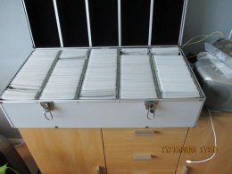
Then came terabyte hardisks... 3 4 TB disks in use, 2 1 TB...
Music just a click away.
https://panteltje.nl/panteltje/newsflex/download.html#xmpl
Loading Image...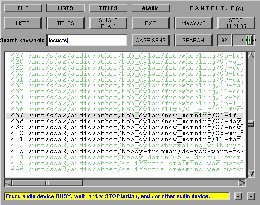 Loading Image...
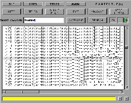 Loading Image...
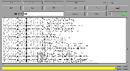
In Linux 'updatedb' makes a list of everything on your system
'locate .mp3' will then find all mp3 etc
and in xmpl you can select some, make playlists etc..
I have an audio equalizer too
Loading Image...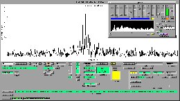
latest xpsa spectrum analyzer also has FM stereo decoding...
Loading Image...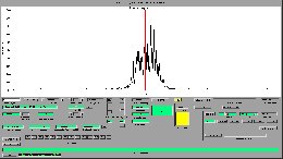
Big stage amplifier here, big boxes...
Playing Fazley keyboard every day... Still learning
https://www.bax-shop.nl/keyboards/fazley-fkb-120-keyboard
cannot make something like that for 110 dollars! No idea how they can make that. has decent speakers too.
PLayed trumpet in the sixties, guitar in the seventies...
The Fazley keyboard allows me to practice without freaking anybody out (using headphones) when I make mistakes...
Plenty of good old audio tracks can be heard and recorded from Astra satellite.
No idea if they got it from tape or vinyl
I still have some old audio cassettes... and a casette player.
Post by Liz TuddenhamWhen playing 'shellac' records (which contain a lot of abrasive) the
roughness on one groove wall displaces the stylus at an angle up and
down the slope of the opposite groove wall. On an X-Y display, without
any modulation this looks like a letter 'X' but the angles of the two
arms of the 'X' may not be at 45 degrees.and may be unequal or even
change as the record revolves. I am dealing with material that may have
been badly recorded and will almost certainly have been damaged by poor
storage and massive playback devices (with heavy resonances). The
'scope is there to enable me to identify and correct as many of the
defects as possible.
Post by Jan PanteltjeElse get a cheap CRT?
https://www.ebay.com/b/oscilloscope-tube/bn_7024937658
There seem to be quite a few to choose from - and I have a couple
complete with their chassis in the attic. It looks as though I am going
to be short of space in the equipment I am designing, so perhaps the
oscilloscope will have to go as a separate item anyway.
Post by Jan PanteltjePost by Liz TuddenhamPost by Jan PanteltjeKnowing programming is almost a requirement these days (since the
seventies) in electronics.
I have programmed in Z80 machine code, Algol, Basic, Applescript, PHP
and HTML, but have only used the last two recently. I also don't have
any programming tools as all my designs are analogue.
Anyways, there is a lot to play with...
https://panteltje.nl/panteltje/pic/jppp18/index.html
https://panteltje.nl/panteltje/raspberry_pi_noppp/
PIC asm is not that hard...
One builds up libraries over time.
That's what a friend keeps telling me. He advocates even the simplest
jobs being done with a microprocessor - but then he never seems to
produce anything that works. At least yours appear to be built and
working.
Yep the intention is to make things I want to use :-)


