Spehro Pefhany
2004-04-21 12:00:25 UTC
Hi all,
A hobbyist has asked for help using a mechanical encoder in the
following circuit:
http://pages.interlog.com/~speff/usefulinfo/dec_circuit.pdf
Looks like he's generating up/down pulses to simulate keyboard presses
(using the analog switches) from the quadrature outputs.
The problem is that circuit (he says) works fine with this kind of
encoder:
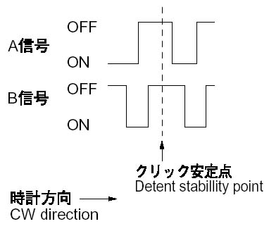
Loading Image...
Which has guaranteed high B signal (high means that the mechanical
switch is "closed" in this case) at the detent.
He wants to use it with this type (from me)
http://www.trexon.com/pdfs/trexon_encoder_revA.pdf
Where the B signal can be either high or low at the detent, and may
actually change if the switch is teased.
Normally I'd do this with a microcontroller by sampling the two
signals at a few hundred Hz and monitoring state transitions (legal
and illegal) after debouncing (looking for states stable for a couple
of samples). This works very well and is reliable. I've also done it
by locking out additional changes by latching a bit. Either way works
fine, in C, 8051 ASM or PIC ASM.
Restricted to logic gates and hopefully adding few parts, can anyone
suggest a fix to this circuit that will allow it to work with either
type of encoder?
Best regards,
Spehro Pefhany
A hobbyist has asked for help using a mechanical encoder in the
following circuit:
http://pages.interlog.com/~speff/usefulinfo/dec_circuit.pdf
Looks like he's generating up/down pulses to simulate keyboard presses
(using the analog switches) from the quadrature outputs.
The problem is that circuit (he says) works fine with this kind of
encoder:
Loading Image...
Which has guaranteed high B signal (high means that the mechanical
switch is "closed" in this case) at the detent.
He wants to use it with this type (from me)
http://www.trexon.com/pdfs/trexon_encoder_revA.pdf
Where the B signal can be either high or low at the detent, and may
actually change if the switch is teased.
Normally I'd do this with a microcontroller by sampling the two
signals at a few hundred Hz and monitoring state transitions (legal
and illegal) after debouncing (looking for states stable for a couple
of samples). This works very well and is reliable. I've also done it
by locking out additional changes by latching a bit. Either way works
fine, in C, 8051 ASM or PIC ASM.
Restricted to logic gates and hopefully adding few parts, can anyone
suggest a fix to this circuit that will allow it to work with either
type of encoder?
Best regards,
Spehro Pefhany
--
"it's the network..." "The Journey is the reward"
***@interlog.com Info for manufacturers: http://www.trexon.com
Embedded software/hardware/analog Info for designers: http://www.speff.com
"it's the network..." "The Journey is the reward"
***@interlog.com Info for manufacturers: http://www.trexon.com
Embedded software/hardware/analog Info for designers: http://www.speff.com