On a sunny day (Fri, 20 Sep 2024 08:10:36 -0700) it happened john larkin
Post by john larkinPost by Jan PanteltjeOn a sunny day (Thu, 19 Sep 2024 14:15:48 -0700) it happened john larkin
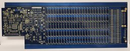
Post by john larkinCan't wait to see this one built. It's an 8-layer board with 2 oz
copper on all the inner layers.
https://www.dropbox.com/scl/fi/x083h0w96p9ihlbvidemp/P948A_PCB_Top.jpg?rlkey=5plqemb1n1k7ioso7olioovnp&raw=1
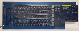
https://www.dropbox.com/scl/fi/sq7ac00n2ysy4r7pjjr3e/P948A_PCB_Bot.jpg?rlkey=y1sjpga50q5dlawe4058fsqov&raw=1
The bottom side has surface-mount relay drivers, shift registers and
sot-23 fets, and the thru-hole relay pins are selective-soldered.
I hope that all works.
Is it easy to replace a defective relay?
No, which is why there are so many polyfuses, to protect the relays
and the PCB traces.
I just measured some trace resistances. I specified 2 oz copper on the
inner layers, and I know that PCB houses often cheat down on copper.
This one is good, conductivity about 8% better than 2 oz.
Post by Jan PanteltjeWhy use relays?
Is that the inductor switching thing you were talking about long ago?
It's a FITS, a cable fault insertion unit. AKA guillotine box.
Cool!
Post by john larkinImagine a system with two boxes connected by a cable. Now chop the
cable and insert this board in the middle. It can simulate any wire
open, any shorted to any other, any shorted to ground. It can measure
and snap waveforms of any voltage or current and can measure
resistances.
Exception would be somebody putting mains power or some high voltage or high current supply line
on a shorted signal lead ?
(fire, cable insulation melts or is damaged, power cables touch signal cables, real possibility in some aircraft crashes that happened.
Was watching one of those series about airplane crashes that happened and were evaluated by experts
where they found that overheated wheel brakes (not relased properly during take off), when the landing gear was pulled in, caused fire in the wings
causing signal cables to be burned... snd shorted, they though it was engine fire (wrong instrument readings),, but was really whole wing on fire, they did a Mayday
and retured but crashed during landing and everybody died.
Post by john larkinThis board does 24 channels but boards can be connected for bigger
cables.
It plugs into our modular power system
https://highlandtechnology.com/Category/MPS
Impressive, I presume you are targetting a specific customer?
Camera a bit out of focus to hide the XXXXX components?
Post by john larkinThat all started when one of our customers, on a zoom call, said "we
hate power supplies!"
Ah yes.
Post by john larkinI think I'll design the 8-channel power supply board next. It could
have some interesting variations, torque motor drivers or something.
There are always limitations to reality simulations though..