John Larkin
2024-08-11 18:53:20 UTC
I want to use an Raspberry Pi 400 (the keyboard thing) as the
dev/debug system for an RP2040 based product.
https://www.amazon.com/Raspberry-Computer-Keyboard-Layout-Kabel/dp/B08QCQVWH2
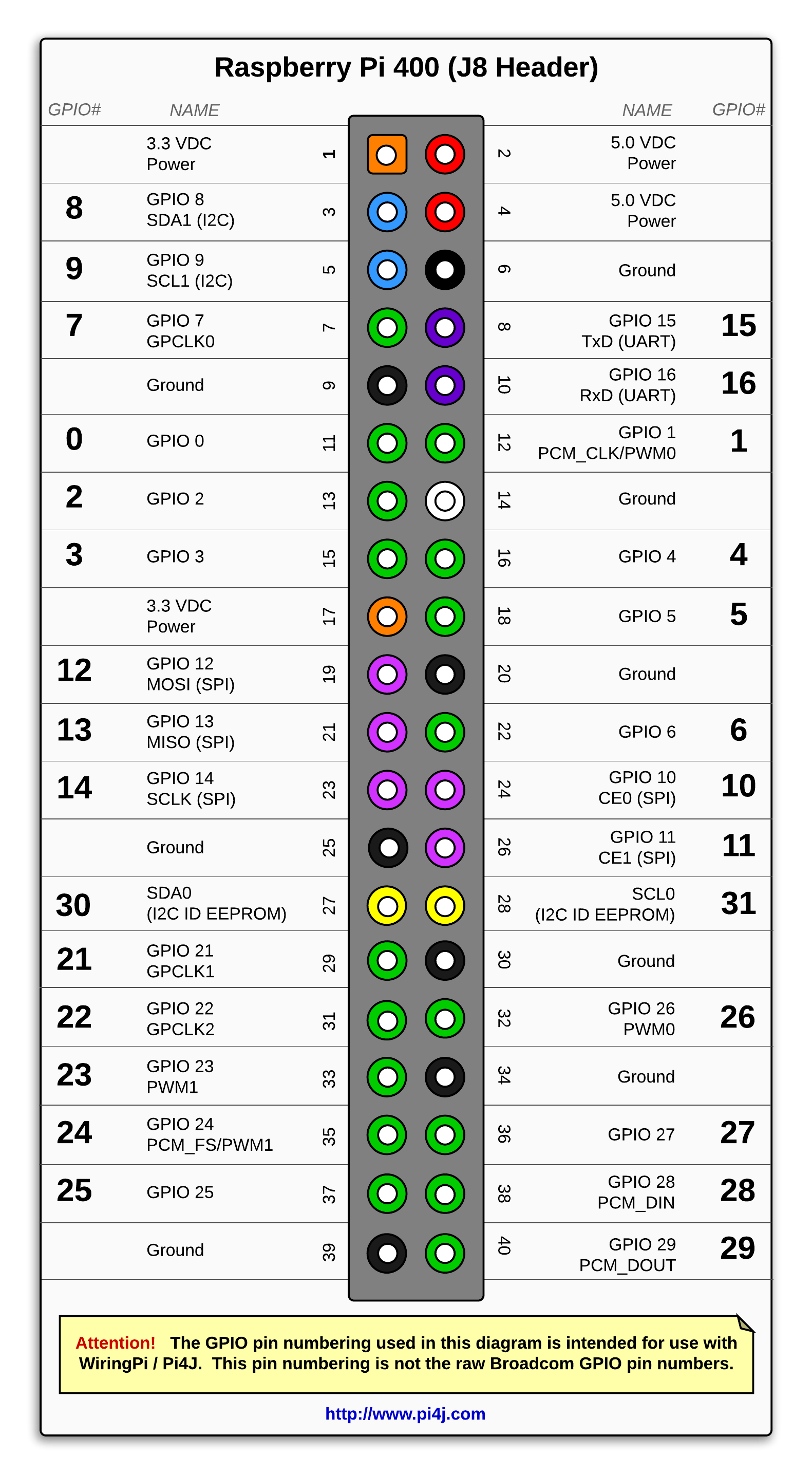
It has a 40-pin connector on the back. Various sources say that pins 1
3 and 5 are either GPIO ports 8 9 and 7 or maybe 2 3 and 4.
Sometimes the pins are labeled WPI and BCM. Wot's that?
https://www.amazon.com/Coolwell-Waveshare-Raspberry-Adapter-Expansion/dp/B08RZCR7S8
I can fix most mistakes there in software, just by reassigning port
names. But two pins are critical, the SWDIO and SWCLK debug lines out
to a Pi Pico or to the 2040 chip.
I suspect that on the Pi 400 pin 18 is GPIO5 = SWDIO and pin 22 is
GPIO6 = SWCLK.
Is that right? Does that actually work?
I also note that some people also connect the UART tx/rx between the
Pi400 and a Pico for debugging. Should I do that too? Does it help
software development?
Thanks!
dev/debug system for an RP2040 based product.
https://www.amazon.com/Raspberry-Computer-Keyboard-Layout-Kabel/dp/B08QCQVWH2
It has a 40-pin connector on the back. Various sources say that pins 1
3 and 5 are either GPIO ports 8 9 and 7 or maybe 2 3 and 4.
Sometimes the pins are labeled WPI and BCM. Wot's that?
https://www.amazon.com/Coolwell-Waveshare-Raspberry-Adapter-Expansion/dp/B08RZCR7S8
I can fix most mistakes there in software, just by reassigning port
names. But two pins are critical, the SWDIO and SWCLK debug lines out
to a Pi Pico or to the 2040 chip.
I suspect that on the Pi 400 pin 18 is GPIO5 = SWDIO and pin 22 is
GPIO6 = SWCLK.
Is that right? Does that actually work?
I also note that some people also connect the UART tx/rx between the
Pi400 and a Pico for debugging. Should I do that too? Does it help
software development?
Thanks!